Preface
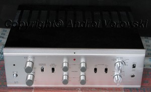 After restoring my Fisher 400, I could not let my smart head and creative hands rest. So I have started to look for another tube gear to apply my newly acquired skills. There was plenty of stuff around, but importing from USA to European Union is quite prohibitive – around $200 – $250 only for shipment plus domestic VAT and customs. I am was very eager to buy Sansui 1000a or Luxman, but none of them appeared in Europe for a reasonable price level. So after all, I took a look at Pioneer SM-83 integrated tube amplifier, which time to time appears on eBay. I found a nice web site called “Fonar” in Poland which has quite detailed photos of internals, and I am was somewhat obsessed. Pioneer tube amp doesn’t have something I hate in other vintage devices – namely large can caps (or anything else) soldered or riveted straight to the chassis (its a hell work to remove them). Finally, I have managed to buy one from France for 300 EURO. Additionally, I have occasionally met nice Finish radio junkie Jouko Kuisma which has bought the same amp in Germany. Of course, I have followed my own golden rules purchasing this Pioneer. However, it was not saved me from some unpleasant caveats.
Posting Photos
This kind of walkthrough is absolutely useless without high-resolution, detailed photos, and that represents a problem. Web pages with plenty of large graphics are slow to load, render and scroll. So I am posting medium-resolution photos straight on the page, with links to view/download larger (around 2500×1200) ones. Click on the image, you will be redirected to a separate page. Click once more to view/download images.
At a Glance
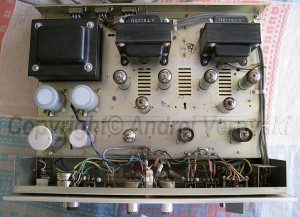
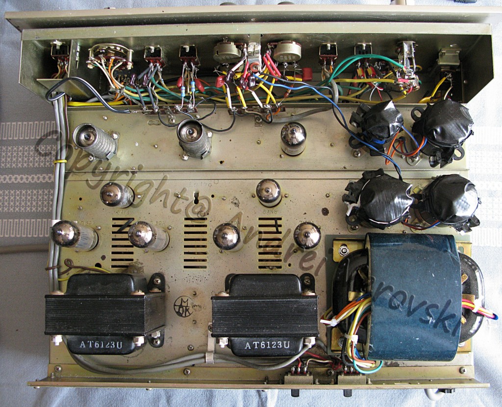
Pioneer SM-83 is a typical vacuum tube integrated amplifier of the 60th era – very solid and heavy steel chassis, 5mm thick aluminum brushed faceplate (unlike Fisher’s this one is somewhat rough), 12AX7 pre-amplifier, 6AN8 medium-mu triode/sharp cut-off penthode inverter, class AB push-pull 7189a output stage with 460V plate voltage (claimed RMS was 28W per channel driving 7189a to the utmost edge), and a couple of nice Tamura (Tamradio) output transformers (Tamura still in the business today as one of the largest Japanese transformer manufacturers). Construction is very smart, there are no rivets, no parts soldered straight to the chassis except few grounding cables, so the amplifier could be very easily disassembled apart. The quality and layout of the assembly are very logical and accurate.
 |
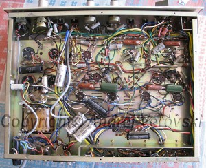 |
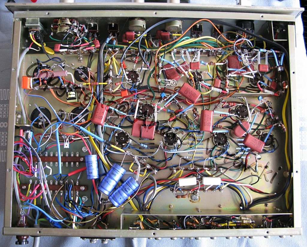
| Top and Bottom (Circuit) Before Restoration | |
Additionally, there are no PEC (packaged electronic circuit) modules (small sets of resistors and capacitors sealed in tiny epoxy case) often used in vintage amplifiers, only discrete parts.
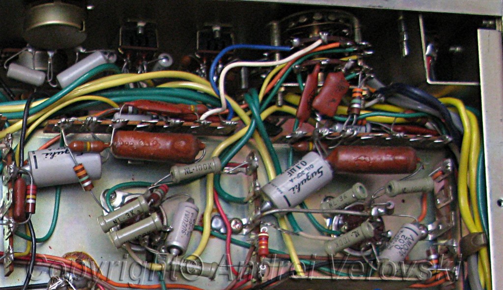
What I immediately discovered all these niceties come at the hefty tax – density of circuits probably at least twice of Fisher 400 (a most likely result of Japanese addiction to miniaturization). Tube electronics in Japan were assembled manually by girls who are known to have very small and thin fingers – making it very difficult service labor for the average man. Need to say, most of Japanese tube tuners/amplifiers (Pioneer, Sansui, Trio/Kenwood) used very similar schematic (with 6AN8 inverter), and components, like Suzuki paper-in-oil capacitors (gray cylinder-shaped objects on the photo left). Another high-rated Japanese electronic manufacturer – Luxman – used mostly Williamson type schematic in his amplifiers.
First Check
The amplifier was in decent condition. it was in a working state, but it clearly required some maintenance. It used heavily by previous owner(s) – volume potentiometer was scratchy beyond cleaning, and balance was simply put broken, in certain positions resulting in loud hum. Pioneer SM-83 seems to have its own strange Achilles heel – resistors. Several carbon resistors were completely out of tolerance. ALL potentiometers manufactured by Noble are clearly not of noble quality – they went from 500k to 800k. One electrolytic capacitor in 6AN8 cathode circuit was exploded. All large can caps in the power supply shown normal capacitance, however, for safety reasons they have to go away. Many experts blame leaking Suzuki paper-in-oil capacitors for output tube damage, Jouko reported the same problems. Taking into account that these amplifiers are 40+ years old, its not bad after all.
Some people think of Japanese tube electronic as second class in terms of quality, however, it is completely wrong. They are not high-value collectibles like McIntosh, but these amps represent probably almost maximum quality possible at the mid-range price level. After all, home electronics is very simple by its nature, it is not a nuclear ballistic missile or space station which requires very special material and assembly parts. “The difference between professional and armature amp builders is pros use as inexpensive parts as possible and develop unique (good) sounding amps. Armatures pick too many expensive parts and end up with less attractive (flat) sounding amps.” – Mr Ohshima, former manager of High-End Department of Sansui.
Restoration Plan
Because of bad resistors, the overhaul plan becomes more complex (or complete?). Checking all old resistors is quite time-consuming task required a lot of disordering, and occasionally may result in leaving bad parts, so I decided to replace all (80+) of them. Coupling caps, paper-in-oil Suzuki, along with electrolytes have to go away, too. In fact, only transformers, few tubes which have not been worn yet were left. And of course, good Pioneer schematic. 2 different scans available here and here.
Restoration Kit Overview
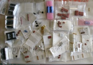
The list of required parts becomes rather long, over 110 items total.
Electrolytic caps: EPCOS 560 UF 400v D35xL40mm 105C, Panasonic 270 UF 450V D35xL30mm 105C, Panasonic 100 UF 400V D25xL30mm 105C, Vishay/BC 63V 330UF Axial D12.5xL30 125C, and few others. Caps are selected for easy stacking, substituting 2 multi-section units, 8 pcs will be used to assemble 4 couples. Please note all caps are at least 105C degree rated!
Coupling and other caps: Panasonic metal propylene 630V, CDE silver mica 500V, TDK multilayer ceramic.
Resistors: Vishay metal film (with low temperature coefficient), Huntington silicone 10W, Yageo wire-wound 5W.
Diodes: Vishay rectifier bridge 6A 600V (for BIAS), Vishay fast recovery 800V/5A for voltage doubler.
Vacuum tubes and few other items (i.e. clamps) are not shown.
Replacement vacuum tubes: for phono stage low-noise Sovtek 12AX7LPS (long plate spiral filament), for pre-amplifier 6N2P-EV (Russian version of 12AX7 with slightly different filament connection), NOS RCA 6AN8, output tubes 6P14P-EV (Russian analog of 7189a). “EV” suffix means military-grade – extended lifetime, 4000 – 5000+ hours. These EV-series tubes known among many audiophiles to have aurally pleasant sonic signature. Although my Hitachi 6AN8 and RCA 12AX7 were still functional, I decided to roll another set of tubes in order to compare sound reproduction quality.
You can download BOM (bill of material) here. Its an OpenOffice spreadsheet containing list of spare parts I have ordered. Please note there are some alternative (duplicate) parts, as well as few items for another project (at the end of the list).
First Steps – BIAS and Power Supply Overhaul
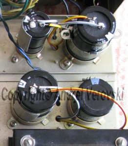
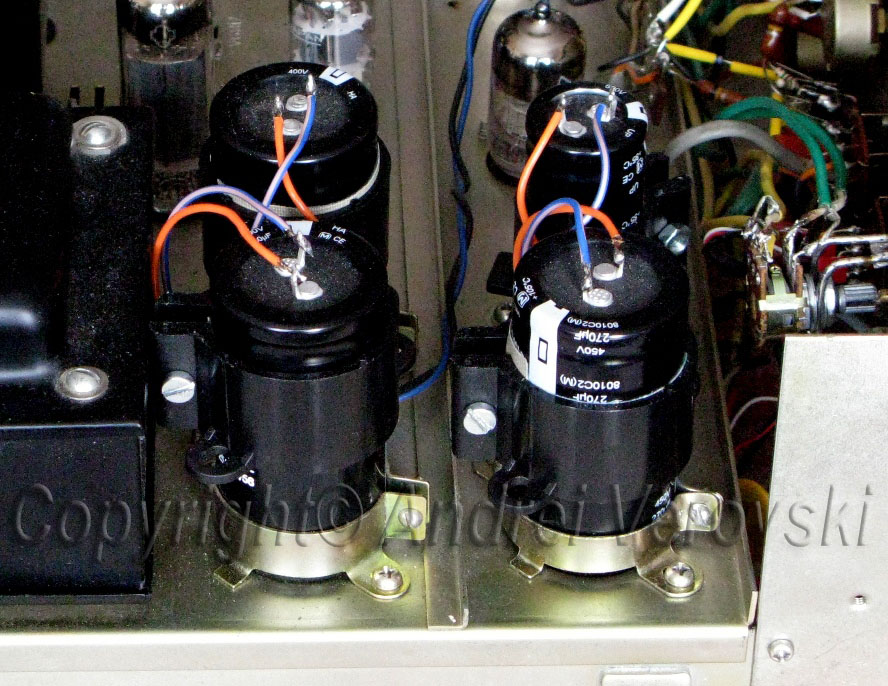
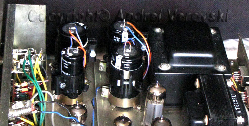
This part of restoration appears to be much easier and less time consuming compared to Fisher 400, since there are no can caps soldered/riveted straight to the chassis. New Epcos and Panasonic caps perfectly fit into clamps instead of old Elna and Nippon Chemi-con. Vishay diode bridge screwed in where the old selenium rectifier was.
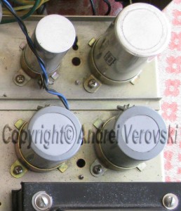
I have eliminated all multi-section caps completely (for the previous project I still used one). Stacking allowed to substitute hard to find multi section caps with 2 general-purpose and affordable ones. I think I found the best, simplest, and least cumbersome way of stacking using just one nylon clamp. The pictures are shown below. Additional to simplicity, stacking with nylon clamps has one important advantage – they are relatively soft compared to metal, and therefore, much less likely to damage thin aluminum cans of electrolytic caps.
|
New can caps (side view) already stacked & assembled with nylon clamps. |
|
When working with high-voltage power supply, do not forget to discharge the filter capacitor – they may hold lethal voltage for a quite long time. You can perform first-step discharge quite simple – connect dummy load (8 Ohm 50W resistors) to the speaker’s terminals, and put some signal into the amplifier – e.g. from mp3 player or generator, then disconnect power, while “playing”. Within 10 – 15 seconds, tubes will still be drawn power from filter caps, discharging them to a low level. Then you can just short cap connectors with a screwdriver for example. Without “dummy play” discharging shortening cap’s contacts may eventually damage them.
After rebuilding BIAS do not forget to install 10 Ohm 1W cathode resistors (between 7189a cathode and ground, not on the schematic). They will act as fuses in case of shorts within tube and hopefully may prevent burning primary winding of audio transformer. Additionally, they are indispensable when it comes to measuring idle current over power tubes (it should be 30 – 33 mA, or 300 – 330 mV over cathode protection resistors). Before the first smoke test, BIAS pot should be at the lowest resistance point, therefore putting much possible negative voltage to the grids of output tubes, and thus, reducing the idle current. Wait for a couple of minutes, and then slowly decrease BIAS voltage, measuring idle current over all 4 output tubes, not just one! If tubes are not matched well, the idle current may be different as much as 20% or even more.
Power supply check has nothing special to say about – everything is limited to measuring the voltage at certain points.
I found one thing which is common for all-tube amplifiers with unregulated power supply and lack of true CLC filter – high sensitivity to surges on 220V power line, resulting in loud clicks when for example refrigerator turns on or off. I have a solid-state Sansui integrated amplifier and it has no audible feedback to these surges whatsoever. There is so little free space in this SM-83, so it is not possible to mount 5 – 10H filter choke under the chassis. I found a tiny room for a small toroidal choke, but it has not reduced unpleasant clicks. And this is despite I have installed 2 x 560 uF in voltage doubler, and 100 uF afterward choke. UPS seems to be the only remaining solution.
Potentiometer & Switch Dilemma
 |
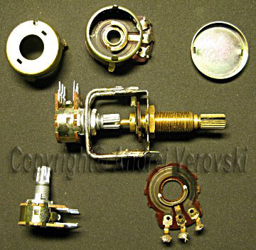 |
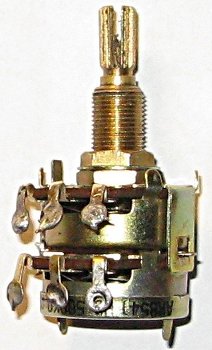
As I mentioned before, there was no good potentiometer left after 40 years of usage. 2 potentiometers represent biggest obstacle – unusually long-shaft 2-gang, 500K log for volume (with a tap from the middle for loudness circuit), and 500K linear balance control. The first one was replaced with a very similar pinned-step 250K from Marantz integrated amplifier (threaded bush and shaft were a little bit shorter but I re-tooled the knob). Of course, caps in the loudness control circuit had to be updated accordingly. With the balance pot, I have stuck completely – nothing similar was found anywhere. Moreover, it cannot be replaced with just similar, it had to be exactly the same – its bush is used to attach faceplate to the front panel !!! In fact, any pots imaginable were available from Alpha Taiwan, but with the minimum order quantity 10,000+. Having no choice left, I took apart the old 2-gang pot almost completely leaving only the shaft and threaded bush, and assembled a “combined” potentiometer with the skeleton of the old one and new miniature 2-gang linear guitar pot (see pictures below).
Another problem popped with the input channel selector switch. Probably it was not used at all during all these 40 years, so all parts become bound together with stoned dust and dirt, and when I turned it, the selector disk falls into pieces. 2-deck 5-pole rotary switches are available in all shapes and colors, but again with different threaded bush and shaft. Another caveat was exceptionally cramped space near that switch. After all, I decided that I do not need microphone and crystal phono inputs, and installed a miniature plastic 2-deck 3-pole rotary switch (AUX-Tuner-Phono only) with a long shaft cut off. Additionally, I have replaced original Pioneer’s exceptionally ugly all-plastic knobs with aluminum ones styled somewhat similar to the ones used for potentiometers.
The Rest of Surgery
During my soldering works, I used to use one handy and absolutely irreplaceable tool: Kocher clamps (or Kelly forceps), originally designed for medical surgery and manufactured with high-carbon stainless steel capable to withstand high temperature and various chemicals. Unlike general-purpose tweezers, it has a locking mechanism near the handle, so one can hold a small object. This habit goes back to 80th, when I am was a schoolboy and radio hobbyist, and my father worked at a medical facility. The only drawback of Kocher clamps is that its handles have no insulation, so working with them in high-voltage environment must very cautious.
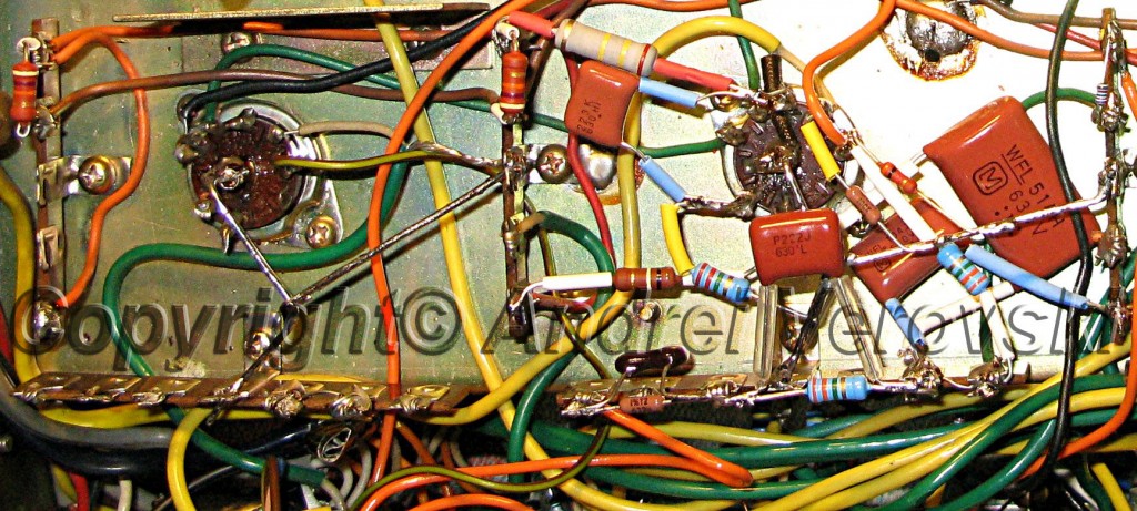
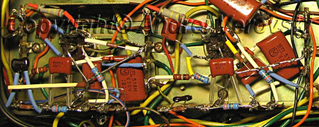
I recommend rebuilding the rest of the amplifier in the following order – output stage, 6AN8 inverter, 12AX7 pre-amplifier, 12AX7 phono amplifier. The latter is the most cramped place. After removing old parts it is recommended to solder thick grounding wires as shown on the image below, they will serve as convenient soldering/mounting points, too.
For whatever reason, plate voltage on 6AN8 and V3 12AX7 was slightly higher than on the schematic, although the voltage on the power rails was in opposite lower. Probably Pioneer’s engineers counted voltage from power outlet as 240V and not 220V in order to avoid output tube overheating in countries like UK, where 240V is common and not 220V like in the rest of Europe.
Due to the dense circuit and a large number of parts to replace it took plenty of time, effort and patience to finish this amplifier.
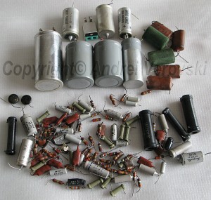
On the photo – parts removed from Pioneer SM-83 during the restoration process. Most of them were still in working condition. All large can caps (Elna and Nippon Chemi-con) were fine, having full capacitance and very small leak value. Few Suzuki paper-in-oil caps had unusually high leak current. After all, I felt like I have cleaned Augean stables.
Q&A
Your questions and feedback is always welcome. Please feel free to contact me, I will post most interesting Q&A material on this page.


Leave a Reply
You must be logged in to post a comment.