Description
After spending plenty of time designing different self-locking bobbins I decided to make an universal tool which would allow to simplify this process.
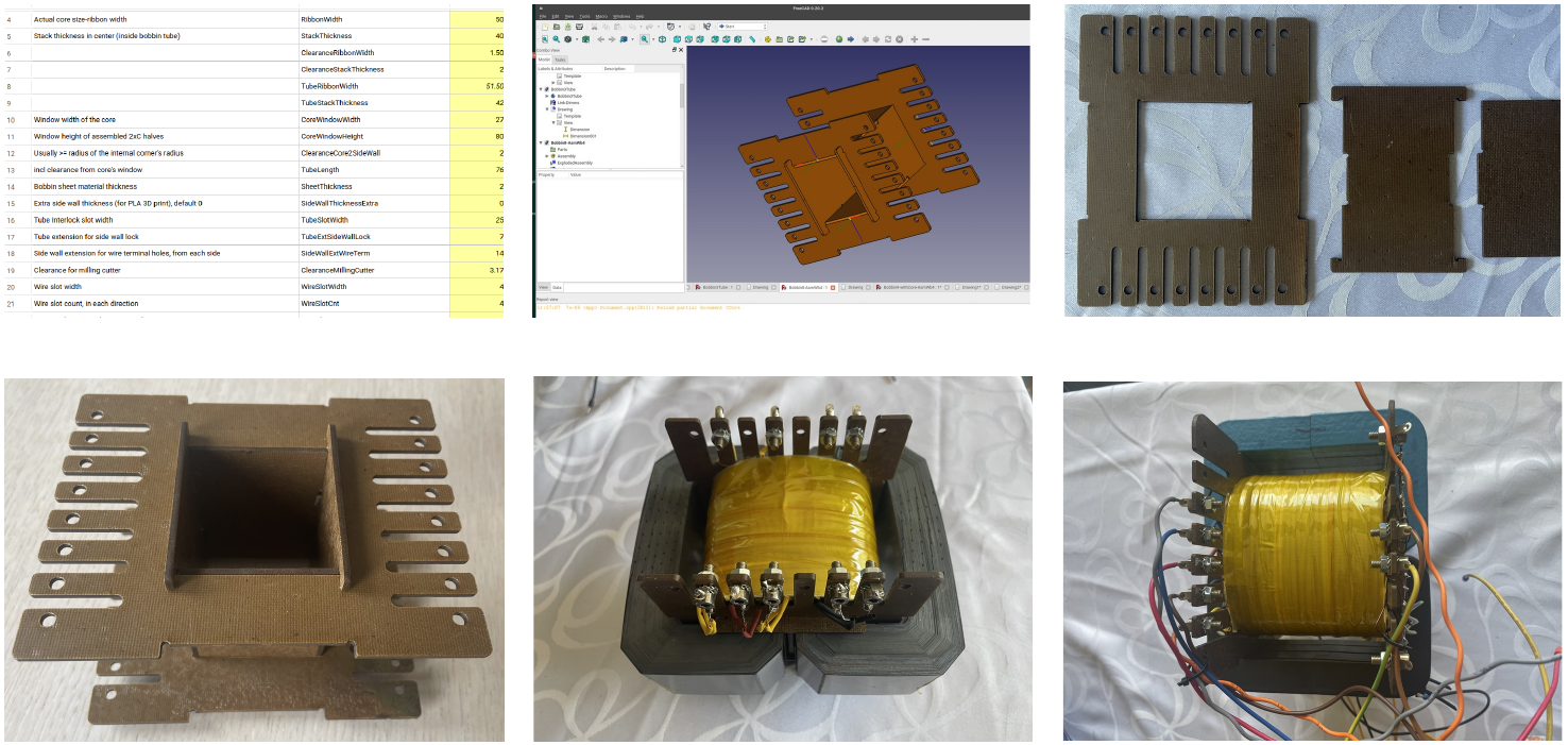
Freeware tool for automatic self-locking bobbin design based on core dimensions – ribbon width, stack thickness (buildup), window height, window width. Can be used for EI, C-core and octagonal wound cores (Unicore). By default generates 3D preview with double C-core. Output files are suitable for laser cutting, milling (with corner clearance for milling cutter with selected diameter), and 3D printing. All necessary geometric parameters are configurable with spreadsheet. Runs within open source parametric 3D modeler FreeCAD, requires Assembly4 + Exploded Assembly workbench, which are optionally installed add-ons (Menu “Tools” – Addon Manager).
Download / Video Tutorial / Links
Download latest (2023-07-18) version here.
License: GNU General Public License V3.0
Platform: any supported by FreeCAD – Windows, Linux, MacOS.
Step-by-step video tutorial for new users, even with zero to little knowledge of FreeCAD.
FreeCAD forum thread.
DIYAudio.com forum thread.
Audiokarma.org DIY forum thread.
Sheet Material
For my own needs I use composite epoxy laminated sheets 2mm thick, which are exceptionally sturdy – largest bobbin made have side wall 177x127mm and coil length 87mm, with finished transformer weight 7Kg. Sheets can be made in home workshop with 2mm presspan (electrotechnical cardboard) impregnated with epoxy used by drone makers. Finished material is similar in properties to CEM and FR4 (glass-reinforced epoxy laminate), but can easly cut with laser just like ordinary veneer.
Files in Archive
File names in archive are self-explanatory. “Asm” suffix means “assembly” – several parts put together. Assemblies are made with Assembly4 workbench, and can’t be updated from an other workbenches like Assembly3 or A2Plus. Unlike many other parametric 3D modelers, FreeCAD have *several* assembly environments.
Base part is “Bobbin1SideWall.FCStd”, with embedded spreadsheet called “Dimms” (dimensions). All other parts and assemblies linked to this spreadsheet to retrieve dimensional data. In order to view and change parameters, you can click on the link in with any part or assembly tree. Important – all 6 source files need to be kept opened all the time you use this tool!
Notes
- Suggested mill corner clearance is 3.2mm for most widely used 3.175mm (1/8”) milling cutter. It may be changed if necessary in spreadsheet “Dimms”. For 3D print or laser cutting I would suggest to set it to 2.0 mm, or remove this feature altogether from the tree.
- Changes in “Dimms” spreadsheet may require forced update of the assembly or tech drawing. Use toolbar buttons “Solve and update assembly” and “Redraw page” respectively as shown on video.
- In case of need more sturdy side walls, e.g. 3mm instead of 2 (SheetThickness), set SideWallThicknessExtra to 1 (2 + 1 = 3). Final model and files will be updated with tube thickness 2mm and wall thickness 3mm.
- UnevenThicknessComp – stock sheet material listed as 2.0mm may have actual thickness anywhere from 1.8 to 2.3mm. Bobbin tube parts from thicker sheets (e.g. 2.3mm instead of 2.0mm) may slightly deform during assembly. To avoid this, define UnevenThicknessComp = 0.2mm as extra relief.
- Octagonal wound cores usually require higher clearance value relative to stack thickness (buildup) compared to C-cores, because they assembled in small segments with step-lap joints (I use 3 – 4mm).
- WireSlotCnt – wire slot count, in each direction. Need to explain, this is *not* total slot count, but rather feature of parametric modeling called “linear pattern” in 2 directions. There is one base slot in the middle of the side wall, and total number of slots in each direction, which *includes* base slot. Thus, if you have this parameter set to 3, you’ll have 5 slots total.
- Changing number of slots updates base geometry, and therefore, some derived features (slot corner fillets) will be broken, leading to unsolvable model. Same happens if you decrease dimensions of the side wall so wire slots can’t fit it anymore. Thus, if you need to change number of wire slots, delete these features from Bobbin1SideWall tree – “Fillet001-wire slots” and .“Fillet001-wire slots”.
- TechDraw – if you modify 3D model then dimensional objects on drawing are very likely to break, because faces and edges will be renamed internally. This is well known FreeCAD’s “topological naming problem” which currently (version 0.20.2) have no simple straightforward fix. Therefore, it is recommended that dimensions (ctrl + left-click to select necessary lines) be added as last step in manufacturing files preparation.
- STL export for 3D print. Select body from tree and then “Mesh” menu -> “Create mesh from shape…”. Use default parameters. Right mouse click on mesh object, select from pop-up menu “Export mesh…” in order to create STL file.
- xBobbin1SideWall-ReinforcementRibs-3DPrint.FCStd – a variant of size wall with reinforcing ribs, created just for curiosity for 3D print. Since plastic used for 3D print is not as sturdy as composite epoxy laminate, you may want to re-enforce it if a bobbin is relatively big. You need to carefully set value of “ClearanceCore2SideWall”. This model considered as draft as an example only, consider using SideWallThicknessExtra if necessary.
Leave a Reply
You must be logged in to post a comment.